![]() ISSN 0798 1015
ISSN 0798 1015

![]() ISSN 0798 1015
ISSN 0798 1015
Vol. 38 (Nº 52) Year 2017. Page 37
Alexandr ORLOV 1; Sergey VOLKOV 2; Alexey SAVELYEV 3; Ilsur GARIPOV 4; Alexey OSTASHENKOV 5
Received: 09/10/2017 • Approved: 21/10/2017
ABSTRACT: A mathematical model of a transformer that takes into account the type of magnetic circuit, as well as losses in its constructive elements from zero sequence currents is proposed. The nature of the dependence of the transformer losses on the difference in the conductivities of the loads of individual phases is shown with the total conductivity unchanged. Based on the results of computer simulation, the relationship between the total power losses and the unbalance coefficients of the zero and negative sequence and coefficient of asymmetry is determined. An estimate is given for reducing additional power losses in transformers when using a three-phase load equalization device. The appearance of the experimental sample of the load balancing unit is presented. key |
RESUMEN: Se propone un modelo matemático de un transformador que tiene en cuenta el tipo de circuito magnético, así como las pérdidas en sus elementos constructivos a partir de corrientes de secuencia cero. La naturaleza de la dependencia de las pérdidas del transformador en la diferencia en las conductividades de las cargas de fases individuales se muestra con la conductividad total sin cambios. Con base en los resultados de la simulación por computadora, se determina la relación entre las pérdidas totales de potencia y los coeficientes de desequilibrio de la secuencia cero y negativa y el coeficiente de asimetría. Se proporciona una estimación para reducir pérdidas de potencia adicionales en transformadores cuando se utiliza un dispositivo de ecualización de carga trifásica. Se presenta la apariencia de la muestra experimental de la unidad de equilibrio de carga. |

Unbalanced load conditions are common phenomenonin 0.4 kV electric mains. A systematic load inequality by phases can occur even in qualitatively designed electrical networks when they grow. Unbalance of currents is the cause of voltage deviations at points of load common coupling. In some cases, such deviations exceed the values adopted in the standard [4], which can lead to negative consequences for the electrical equipment of end users. [11]
Unbalanced load are a source of losses in the elements of electrical mains. The relevance of this problem is confirmed by large number of papers. For example, in work [8, 10] authors present algorithms and computer programs for determining the energy losses in the elements of electrical mains caused by decrease in the quality of electricity. In work [10] Miroshnik A.A. estimates the degree of energy losses in case of unbalancing load. In [5, 6, 7] Ded A.V. et al. describe the influence of non-symmetry on power losses in various elements of electrical mains.
There are papers dedicated to various ways for reduce the asymmetry of currents and voltages. For example, in [12, 13, 14, 15] is considered the load balancing device redistributing the load between the phases of the electrical main and the algorithms of its operation.
There are known papers devoted to the modeling of transformers and the determination of additional losses in them with asymmetry. The paper [16] gives a mathematical model in time domain of a three-phase transformer with a common magnetic core taking into account the loss of steel. The work [3] is devoted to modeling of a transformer with a three-rod magnetic core in frequency domain. The model proposed by the authors makes it possible to calculate the magnitudes and angles of currents and voltages in the windings. A number of other works are devoted to the problem of minimizing losses in power transformers, for example, [9, 17]. The losses in the constructive elements of the transformer induced by zero sequence magnetic fluxes are a significant component of the losses in the presence of zero sequence currents. Accounting for this factor in the modeling of transformers, along with the development and research of methods for reducing losses, seems to be an urgent task.
The purpose of the paper is to investigate the transformer losses at unbalanced loads, based on the mathematical model of the transformer, as well as in evaluating the effect of the load balancing device on losses in transformers. Scientific novelty of the work is to develop a mathematical model of a transformer in time domain, taking into account the type of magnetic core and the losses in constructive elements from zero sequence magnetic fluxes, as well as to evaluate the effect of the load balancing device on reducing additional losses in transformers.
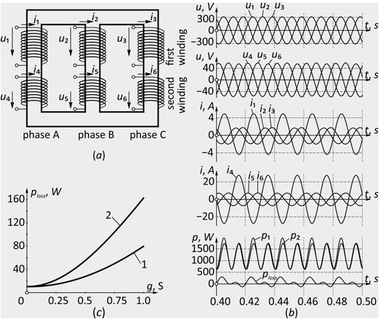
A three-phase two-winding transformer consisting of 6 inductively coupled coils, 2 for each phase, Fig. 1 (a). Each coil in the mathematical model is represented as an active-inductive loop. The contours have a certain inductive coupling between themselves, additionally depending on the type of magnetic circuit. The losses in the constructive metallic elements of the transformer resulting from the circuiting of zero sequence magnetic fluxes through them is made in the model by adding an additional short-circuited contour (the parameters of which are denoted by the index sc), which has a low inductive coupling with the coil circuits. The saturation of the magnetic core in the model was not taken into account.
Fig. 1
(a) The designations of the windings of a three-phase transformer and one of
inductively coupled circuits. (b) Oscillogram of the main electrical quantities
of the transformer. (c) Dependence of the total power losses ploss on the total
conductance of the load g: 1 – with a symmetrical load; 2 – with an asymmetrical load.
The approach described in [2] was used in developing the mathematical model. The mathematical description of the transformer model was considered in the form of a first-order ODE system in matrix form.
The calculation of electromagnetic processes in the transformer was carried out for direct connection to a symmetrical three-phase system of voltages at different loads Ra, Rb, Rc. The nature of the load is chosen to be purely active due to its wide distribution in distribution networks of 0.4 kV. The connection scheme the Y/Y0 windings. The ODE system (1) was solved numerically with respect to the column vector of the current I with zero initial conditions. To solve the system of equations and automate a series of numerical experiments, we used the program created by the authors written in Python, which implements the Gauss-Legendre method of 6 order of accuracy. The modeling conditions imply the possibility of changing the load of the transformer within a wide range – from no-load to short circuit – realized in the model due to the time variation of the matrices R and L. Applicable method refers to the group of implicit Runge-Kutta methods and is chosen because of the higher stability of the solutions in comparison with explicit methods.
The transformer ТСЗИ-1,6 with nominal phase voltages of 220/42 V, whose parameters are determined experimentally, was considered as a simulation object. Fig. 1 (b) shows the oscillograms of the main electrical quantities of the transformer, as a result of simulation. The oscillograms correspond to a time interval of 0.4–0.5 s after is direct connecting of the transformer to the electric main with an unbalanced load Ra = 2 Ohm, Rb = 8 Ohm, Rc = 8 Ohm. To exclude the effect of transients on simulation results, the parameters with new input data were determined in steady-state mode on time interval of 2–3 seconds after the start of simulation.
As the value characterizing the total load of the transformer, the total conductivity of the three phases of the load g = ga + gb + gc is chosen. It should be noted that the conductivity of the individual phases load is practically proportional to the currents in them in the operating range of the transformer loads. In order to characterize the unbalance, the unbalance coefficient of the currents in zero and negative sequences K0 and K2 was used, as well as coefficient of asymmetry kasymm = 3∙(Ia2 + Ib2 + Ic2) / (Ia + Ib + Ic)2. This value was used by the author of [4] to estimate additional losses in the elements of the power supply system. For a purely active load in the case under consideration the unbalance coefficients K0 and K2 are equal. In this case the relation between the coefficients of asymmetry kasymm and K0, K2 it is characterized by the expression kasymm = 2 ∙ K02 + 1.
It is known that the total losses of a three-phase transformer include a conditionally constant component associated with magnetic losses and a component proportional to the square of the load amount g2. If g is unchanged, the total power losses of ploss differ, depending on the degree of unbalance. This difference is shown in Fig. 1 (c), in which curves 1 and 2 correspond to the balanced (ga = gb = gc = g / 3) and extremely unbalanced mode (ga = gb = 0, gc = g) by the same total conductivity g.
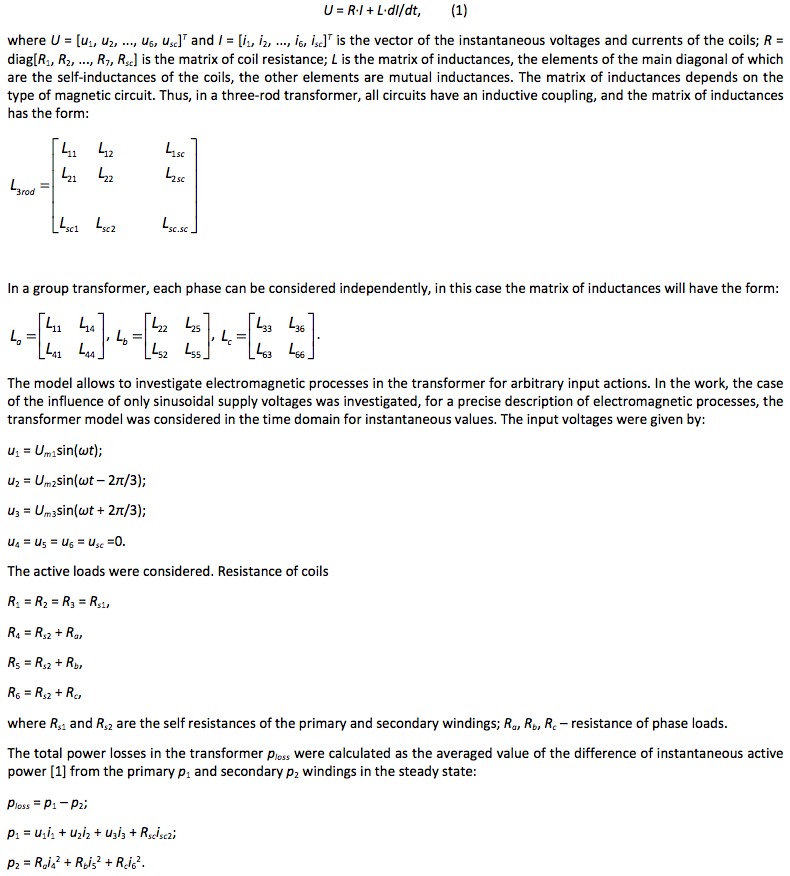
Fig. 2 (a) Dependence of the total power loss ploss by various phase conductivities of loads,
but the unchanged total conductivity g = 0.75 S (b) Dependence of total losses ploss when
the loads of two phases vary in the range from 0 to g/3, and the third phase - from g to g/3.
The purpose of the investigation was also determination of the character of the dependence of the transformer losses on the degree of unbalance for a given total conductivity g = const. For this purpose, the total losses of the transformer were calculated for all practically admissible distributions of phase conductivities ga, gb and gc. By g = const in the coordinates ga, gb and gc the set of conductivity values form a plane in the first octant.
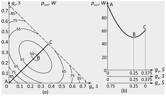
Fig. 2 (a) shows the dependence of the total power loss ploss by different phase conductivities of loads, but by the unchanged total conductivity g = 0.75 S in the form of a contour plot. The graph is based on the results of computer simulation of the transformer with various combinations of phase conductivities of loads. Under the conditions under consideration, the graph is symmetrical with respect to the point with phase conductivities of the load ga = gb = gc = g / 3 = 0.25 S. At a given point total losses ploss are 50 W. With increasing unbalance, the total losses increase and reach a maximum at the corners of the contour plot, where the conductivities of the two phases are zero, and the conductivity of the third phase is g. Fig. 2 (b) shows the total losses when the loads of the two phases vary in the range from 0 to g / 3, and the third phase are from g to g/3, which corresponds to the ABC line in the contour plot in Fig. 2 (a). This is one of the possible ways of changing the unbalance coefficients of currents in the reverse and zero sequences K0 and K2 in the range from 1 to 0, and the load coefficients of asymmetry kasymm is from 3 to 1. Fig. 3 (a, b) shows the dependence of the total power loss ploss on the coefficients of asymmetry kasymm, as well as on the coefficients of asymmetry of the currents in negative and zero sequences K0 and K2. The graphs show that the total power losses of ploss are proportional to K02, K22 and kasymm.
Fig. 3 (a) Dependence of the total losses of the power ploss on the load coefficients
of asymmetry. (b) Dependence of the total losses of the power ploss on the unbalance
coefficients of the currents on the negative and zero sequence K0 and K2.
-----
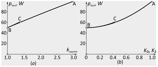
Fig. 4. Appearance of the experimental sample of the load balancing unit.
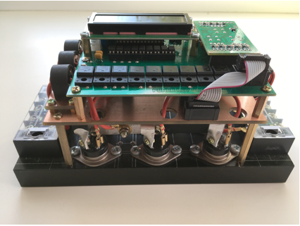
An experimental sample of the LBU for low-voltage distribution networks is shown in fig. 4. The power section of the device is made on 9 triacs mounted on the radiator. The radiator serves as the main structural element of the experimental sample of LBU, and also provides heat removal from the power keys. The triac is controlled by the ATmega 8A microcontroller. To display the current position of the power keys on the controller board, an LCD display is provided. To connect the device to the electric mains and to the load, there are two terminal blocks.
Also in the device there is a set of current transformers for measuring the currents of the outgoing load line connected to the device, as well as a connector for connecting to the phases of the electrical network and a neutral wire for measuring phase voltages by the control system. The interaction of the power key controller and the control system is provided via the UART interface wired or wirelessly by uses the appropriate adapters.
1. A mathematical model of a transformer is proposed that takes into account the type of magnetic circuit, as well as losses in constructive elements from the component of the zero sequence currents.
2. The nature of the dependence of the losses of the transformer on the degree of load asymmetry for a given total conductivity is established.
3. Based on the results of computer simulation, the relationship between the total power losses with the active load profile with zero and negative sequence unbalance currents and the load non-uniformity coefficient is shown.
4. It is shown that the load balancing unit allows, in the optimal case, to reduce additional power losses in the transformer by an average of 48% compared to this value without using the device.
Akagi H. Watanabe E.H., Aredes M. Instantaneous Power Theory and Applications to Power Conditioning. Wiley-IEEE Press, 2007, 379 p.
Krause P.C., Wasynczuk O., Sudhoff S.D. Analysis of Electric Machinery and drive systems. 3rd Edition. Wiley-IEEE Press, 2013, 680 p.
Boshnyaga V.A., Suslov V.M. Modelirovanie trekhfaznykh transformatornykh ustroistv s trekhsterzhnevym magnitoprovodom dlya inzhenernykh raschetov nesimmetrichnykh rezhimov pri razlichnykh skhemakh soedineniya obmotok [Modeling of three-phase transformer devices with a three-rod magnetic cores for engineering calculations of asymmetric modes for various winding connection schemes]. Problemy regional'noi energetiki [Problems of regional energy], 2013, no. 2 (22), pp. 38–50.
GOST 32144–2013. Elektricheskaya energiya. Sovmestimost' tekhnicheskikh sredstv elektromagnitnaya. Normy kachestva elektricheskoi energii v sistemakh elektrosnabzheniya obshchego naznacheniya [State Standart 32144–2013. Electric energy. Electromagnetic compatibility. of technical equipment. Power quality limits in the public power supply systems (EN 50160:2010, NEQ)]. Moscow: Standartinform Publ., 2014, 16 p.
Ded A.V., Volynkin A.I., Denisenko M.Yu., Kirichenko N.V., Sukhov E.S. Dopolnitel'nye poteri moshchnosti v elektricheskikh setyakh pri nesimmetrichnoi nagruzke [Extra power losses in electrical networks with unbalanced load]. Omskii nauchnyi vestnik [Omsk Scientific Bulletin], 2013, no. 1 (117), pp. 157–158.
Ded A.V. Opredelenie poter' moshchnosti v raspredelitel'nykh setyakh s uchetom vliyaniya nesimmetrichnoi nagruzki [Determination of power losses in distribution networks taking into account the influence of an asymmetric load]. Omskii nauchnyi vestnik [Omsk Scientific Bulletin], 2009, no. 2 (80), pp. 167–170.
Ded A.V., Parshukova A.V. Metod rascheta dopolnitel'nykh poter' moshchnosti pri nesimmetrii rezhima raboty sistemy elektrosnabzheniya [Method for calculating additional power losses in case of unbalance of the operating mode of the power supply system]. Mezhdunarodnyi nauchnyi zhurnal "Innovatsionnaya nauka" [International scientific journal "Innovative Science"]. 2015, no. 10/2015, pp. 61–65.
Dolinger S.Yu., Lyutarevich A.G., Goryunov V.N., Safonov D.G., Cheremisin V.T. Otsenka dopolnitel'nykh poter' moshchnosti ot snizheniya kachestva elektricheskoi energii v elementakh sistem elektrosnabzheniya [Estimation of additional power losses due to a decrease of the quality of electrical energy in the elements of power supply systems]. Omskii nauchnyi vestnik [Omsk Scientific Bulletin], 2013, no. 2 (120), pp. 178–183.
Kirisov I.G., Ovcharenko T.I. Minimizatsiya poter' v silovykh transformatorakh pri izmenenii rezhima nagruzki [Minimization of losses in power transformers with changing load conditions]. Energosberezhenie. Energetika. Energoaudit [Energy saving. Power engineering. Energy audit]. 2014, no. 6 (124), pp. 49–56.
Miroshnik A.A. Metody vychisleniya poter' moshchnosti v elementakh nesimmetrichno nagruzhennoi seti [Methods for calculating power losses in elements of an asymmetrically loaded network]. Elektrotekhnika i elektromekhanika [Electrotechnics and Electromechanics]. 2011, no. 5, pp. 66–69.
Kurilin S.P. Razvitie teorii nesimmetrichnykh rezhimov i energeticheskikh protsessov asinkhronnykh dvigatelei sel'skokhozyaistvennykh elektroustanovok: dis. dokt. tekhn. nauk. [Development of the theory of asymmetric modes and energy processes of induction motors of agricultural electrical. Doct. Diss.]. Moscow, 2005, 367 p.
Orlov A.I., Volkov S.V., Savel'ev A.A. Analiz vliyaniya ustroistva vyravnivaniya nagruzki na pokazateli nesimmetrii elektricheskoi seti [Analysis of influence of load balancing unit on indicators of unbalance of power supply]. Vestnik Chuvashskogo universiteta [Bulletin of Chuvash University], 2016, no. 3, pp. 100–108.
Orlov A.I., Volkov S.V., Savel'ev A.A. Algoritmy upravleniya trekhfaznym ustroistvom vyravnivaniya nagruzki elektricheskoi seti [Control algorithms of three-phase balancing unit for power supply network]. Vestnik Chuvashskogo universiteta [Bulletin of Chuvash University], 2017, no. 1, pp. 162–172.
Orlov A.I., Savel'ev A.A. Ustroistvo simmetrirovaniya nagruzki [Load balancing unit]. Patent RF 162639, no. 162639, 2016.
Orlov A.I., Savel'ev A.A. Sposob simmetrirovaniya mnogofaznoi elektricheskoi seti i ustroistvo dlya ego realizatsii [Method of balancing a multiphase power supply and device for its implementation]. Patent claim RF 162639, no. 2016127923, 2016.
Pustovetov M.Yu. Matematicheskaya model' trekhfaznogo transformatora [Mathematical model of a three-phase transformer]. Izvestiya Tomskogo politekhnicheskogo universiteta. Inzhiniring georesursov [Bulletin of the Tomsk Polytechnic University. Geo Assets Engineering], 2012, Vol. 321, no. 4, pp. 97–100.
Yundin M.A., Khanin Yu.I. Dopolnitel'nye poteri elektroenergii v silovykh transformatorakh 10/0,4 kV [Additional power losses in power transformers 10/0,4 kV]. Nauchnyi zhurnal KubGAU [Scientific Journal of KubSAU], 2014, no. 101 (07), pp. 1–11.
1. Mari State University, Yoshkar-Ola, Russian Federation; E-mail: karlorlov@gmail.com
2. Mari State University, Yoshkar-Ola, Russian Federation; E-mail: eef@marsu.ru
3. Mari State University, Yoshkar-Ola, Russian Federation; E-mail: savelich94@gmail.com
4. Interregional Open Social Institute, Yoshkar-Ola, Russian Federation; E-mail: koratos1@gmail.com