![]() ISSN 0798 1015
ISSN 0798 1015

![]() ISSN 0798 1015
ISSN 0798 1015
Vol. 38 (Nº 24) Año 2017. Pág. 17
Dias Raybekovich UMYSHEV 1; Abay Muhamediyarovich DOSTIYAROV 2; Galia Muafekovna TYUTEBAYEVA 3
Recibido: 06/03/17 • Aprobado: 06/04/2017
2. Experimental setup and methods
ABSTRACT: This article presents the results of an experimental study of the management of NOx emissions and their dependence on different types of fuel supple and V-gutter flameholders. On the basis of the experiment the diagrams of the dependence of NOx emissions on the air-fuel ratio (φ) were presented. The mechanisms of NOx formation were discussed. Based on the experimental tests, the authors provided the formula for calculating NOx emissions when using various V-gutter flameholders. |
RESUMEN: Este artículo presenta los resultados de un estudio experimental de la gestión de las emisiones de NOx y su dependencia de los diferentes tipos de bombas de combustible y de cigüeñal V. Sobre la base del experimento se presentaron los diagramas de la dependencia de las emisiones de NOx en la relación aire-combustible (φ). Se discutieron los mecanismos de formación de NOx. Sobre la base de los ensayos experimentales, los autores proporcionaron la fórmula para calcular las emisiones de NOx cuando se usan varios colectores de llama de la V-cúpula. |

Modern gas turbines should have not only very low emissions but also good performance indicators. The analysis of emissions primarily includes nitrogen oxides (NOx). The main causes of NOx formation are a high temperature in the combustion zone and the residence time of gases in the zone of high temperatures (Umyshev et al., 2016; Lefebre, 1986; Khristich and Litoshenko, 1968; Butovskiy and Khristich, 1972; Khristich, G. N. Lyubchik, 1972; Khristich and Tumanovskiy, 1983).
According to D.R. Umyshev, A.M. Dostiyarov, M.Y.Tumanov and Q. Wang (Umyshev et al., 2016), a simple and reliable way to improve the environmental and stabilization indicators of the gas-turbine unit is to use V-gutter flameholders. The reduction of NOx emissions and stabilization is largely determined by the recirculation zone formed behind V-gutters. An optimal selection of the expansion angle and the length of walls, perforations, as well as the fuel supply method can provide an optimal value of the recirculation zone, which provides a relatively low average temperature in the combustion zone, the short residence time of combusted gases as well as good mixing (Umyshev et al., 2016; Lefebre, 1986).
Soviet authors (Khristich and Litoshenko, 1968; Butovskiy and Khristich, 1972; Khristich, G. N. Lyubchik, 1972; Khristich and Tumanovskiy, 1983; Khristich, Patent No. SU 169948) studied various types of V-gutter flameholders and the effect of various parameters such as the fuel supply method, the effect of bridges between V-gutters as well as the air velocity. They considered a number of options for supplying the air-fuel mixture into the combustion zone – the unmixed fuel – diffusion and the mixed fuel - kinetic. The results of these works show that V-gutter flameholders have good potential. Aiwu Fan et al. (Aiwu Fan et al., 2013; Aiwu Fan et al., 2014; Jianlong Wan et al., 2012; Aiwu Fan et al., 2013) carried a deep study of the processes of combustion, stabilization and heat exchange behind bluff bodies. They proved that the process of stabilization significantly depends on the recirculation zones generated behind V-gutter flameholders.
The analysis of these studies shows that V-gutter flameholders in the form of bluff bodies have great potential. Current developments are moving towards the two-stage combustion with the use of bluff bodies.
Figure 1 presents a schematic diagram of the experimental setup, which consists of an air compressor, a section with Ø4 mm flameholding tubes 400 mm long, and a section of a quartz tube 500 mm long. The diameter of the experimental setup is 60 mm, the inner diameter of the quartz tube is 40 mm. The fuel supply system consists of a cylinder with propane (99%), a fine adjustment valve, a flow meter and a copper Ø5 mm tube. At the beginning of the section 500 mm long, one V-gutter and a copper tube are set. At the end of the section, a group of Cr/Al thermocouples and a gas analyzer sampler connected to a personal computer are installed. Maximum fuel consumption is 1.2 kg/h, the air velocity – 1÷10 m/s. The accuracy of the air flow was controlled by an anemometer in two sections of the experimental setup and a flow meter. The error margin of anemometers did not exceed 2%. The error margin of flow meters did not exceed 2% of the measured. The error margin of analyzers did not exceed 3% of the measured values of NOx ppm. To check the received data of the gas analyzer, further control measurements were carried out by the chemo-luminescent method.
Lean blowout was measured as follows: at a certain rate, the fuel decreased from the maximum value until its flames visually extinguished. The value of the flow meter was recorded. The value of φ was calculated according to the formula 1.

where 0.2 is a stoichiometric fuel / air ratio for propane.
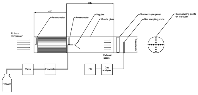
Figure 1. The schematic diagram of the experimental setup
The experiment used four types of V-gutters: a) a normal V-gutter – type 1; b) a large V-gutter – type 2; c) a small perforated V-gutter – type 3; g) a large perforated V-gutter – type 4. The angle at the top of each V-gutter was 45°. The width of small V-gutters was 30 mm, large V-gutters – 35 mm. A general view of V-gutters is shown in Figure 2.
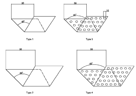
Figure 2. General view of V-gutter flameholders
Figure 3 shows the fuel supply circuits. The experiment considered three types of fuel supply. The first type is fuel supply to the V-gutter walls. This option suggests that the fuel is supplied through two copper tubes to the V-gutter walls from a distance of 20 mm. The second type is fuel supply directly to the V-gutter inner zone. In this type of supply, a copper tube is inserted into the V-gutter at a distance of 5 mm. The third type suggests that the fuel is supplied from the V-gutter bottom along the symmetry axis. The distance between the V-gutter bottom and a copper tube is 20 mm.
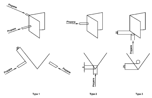
Figure 3. Fuel supply circuits
Figure 4 shows the dependence of NOx emissions on the equivalence ratio φ and the type of V-gutters in variant 1 of fuel supply. It should be noted that in this fuel supply variant, the flames of small V-gutters were stable – 5 m/s. A further increase in their velocity led to a blowout.
Non-perforated V-gutters depend on two factors. The first factor is a high fuel concentration coming to the V-gutter edges. This fact leads to an increase in local zones with high values of φ, which increases the average temperature of the flame. The second factor is the recirculation zone. As mentioned in the previous paper (Umyshev et al., 2016), non-perforated V-gutters have a well-developed recirculation zone at an angle of 45 °. This increases the residence time of gases in the combustion zone, which has local high temperature zones. The sum of these two factors leads to high NOx emissions.
Several factors can be mentioned when considering perforated V-gutters. The first factor is that a large amount of air and a very small amount of fuel is supplied to the V-gutter inner zone. It is also observed that most of the fuel due to the specificity of supply is blown out to the V-gutter edges. The second factor is that the air-fuel mixture coming through perforations destroys the recirculation zone, thereby weakening its force (Umyshev et al., 2016).
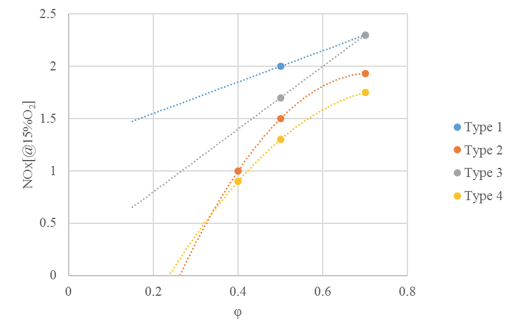
Figure 4. Dependence of NOx emissions on φ and V-gutter type in variant 1 of fuel supply
Figure 5 shows the dependence of NOx emissions on φ and V-gutter type in variant 2 of fuel supply
In this variant of fuel supply, a large section has the highest values of NOx emissions. As noted above, the main causes of NOx formation are the residence time of gases in the combustion zone and temperature. In this case, both factors play a significant role. The sum of such factors as the high equivalence ratio φ in the combustion zone and the increased residence time of gases at the expense of the developed recirculation zone lead to high concentrations of NOx in the exhaust gases.
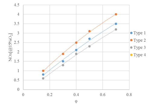
Figure 5. Dependence of NOx emissions on φ and V-gutter type in variant 2 of fuel supply
Figure 6 shows the dependence of NOx emissions on φ and V-gutter type in variant 3 of fuel supply. The maximum values of NOx emissions were observed in large non-perforated V-gutters. This situation is similar to the previous variant. The clean fuel enters the recirculation zone. In the recirculation zone at the expense of too much concentration and insufficient mixing there appear a number of sections with a rich fuel concentration, i.e. a high value of φ. This circumstance determines the development of local sections with high temperatures, which increase the production of nitrogen oxides.
As mentioned above, perforated V-gutters have lower rates.
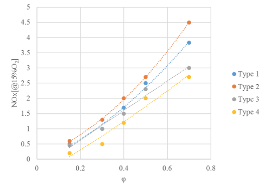
Figure 6. Dependence of NOx emissions on φ and V-gutter type in variant 3 of fuel supply
On the basis of the conducted experiment, the authors present the formula for calculating NOx emissions by using V-gutter flameholders:
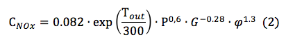
where 0.082 is the mixing empirical coefficient that determines the efficiency of mixing of the air-fuel mixture, Тout – the temperature at the output of the experimental setup, P – pressure, G – the air flow, φ – the equivalent ratio (φ=1/α).
Figure 7 shows a comparison of the results obtained by the formula 2 and the experiment.
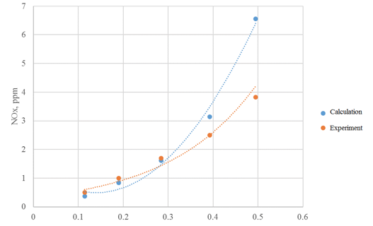
Figure 7. Comparison of the calculations by the formula 2 and the experimental data
On the basis of the conducted experiment, the authors present the formula for calculating NOx emissions by using V-gutter flameholders:
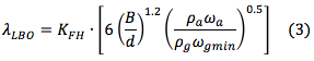
where kFH is the empirical coefficient variable in the range of 0.004-0.013 depending on V-gutter type, B – the width of the V-gutter, d – the diameter of the nozzle, ρа, ωа – the air density and velocity, respectively, ρg, ωgmin – the gas density and flow rate, respectively.
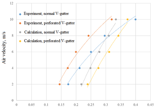
Figure 8. Comparison of the experimental results and calculations by the formula 3
The experimental results allowed the authors to draw the following conclusions:
1) The fuel supply method significantly affects the processes of NOx formation and stabilization;
2) In all fuel supply variants, perforated V-gutters showed the best results of flameholding, with the exception of variant 2, where large sections did not allow the authors to create a stable flame;
3) The lowest NOx concentration was observed when the fuel was supplied to the V-gutter walls. However, this was likely due to the high incompleteness of combustion, as evidenced by the photos.
Aiwu Fan et al. (2013). The effect of the blockage ratio on the blow-off limit of a hydrogen, air flame in a planar micro-combustor with a bluff body. International journal of Hydrogen Energy, 38, 11438- 11445.
Aiwu Fan, Jianlong Wan, Kaoru Maruta, Hong Yao, Wei Liu (2013). Interactions between heat transfer, flow field and flame stabilization in a micro-combustor with a bluff body. International Journal of Heat and Mass Transfer, 66, 72–79.
Aiwu Fan, Jianlong Wan, Yi Liu, Boming Pi, Hong Yao, Wei Liu (2014). Effect of bluff body shape on the blow-off limit of hydrogen, air flame in a planar micro-combustor. Applied Thermal Engineering, 62, 13-19.
Butovskiy, L. S., Khristich, V. A. (1972). The structure of mixing zone and particular qualities of burning behind triangle flameholder. In: Theory and practice of gas burning. Leningrad, pp. 76-82 (in Russian).
Jianlong Wan, Aiwu Fan, Kaoru Maruta, Hong Yao, Wei Liu (2012). Experimental and numerical investigation on combustion characteristics of premixed hydrogen, air flame in a micro-combustor with a bluff body. International journal of hydrogen energy, 37, 19190-19197.
Khristich, V. A. Patent No. SU 169948, The annular combustion chamber of the gas turbine.
Khristich, V. A., Lyubchik, G. N. (1972). About the stability of diffusional combustion behind flameholders. In: Theory and practice of gas burning. Leningrad, pp. 82-85 (in Russian).
Khristich, V. A., Lyubchik, G. N. (1972). The influence of gas fuel type on combustion process of jet-stabilizer burners. In: Theory and practice of gas burning, Leningrad, pp. 12-132 (in Russian).
Khristich, V. A., Tumanovskiy, A. G. (1983). Gas turbine engines and environmental protection. Kiev, Technics, 144 p. (in Russian).
Khristich, V. A., Litoshenko, V. N. (1968). Investigation of the counter flow zone dimensions behind the system of corner flameholders. Herald of KPI. Thermal engineering series, 5, 10-15, (in Russian).
Lefebre, A. (1986). Gas turbine combustion. Moscow, Mir, USSR, (in Russian).
Umyshev, D. R., Dostiyarov, A. M., Tumanov, M. Y., Wang, Q. (2016). Experimental investigation of v-gutter flameholders. Thermal Science Journal, DOI: 10.2298, TSCI151209072U.
1. Almaty University of Power Engineering & Telecommunications. E-mail: umishev_d@mail.ru
2. Kazakh Agrotechnical University named after S.Seifullin.
3. Kazakh Agrotechnical University named after S.Seifullin.