![]() ISSN 0798 1015
ISSN 0798 1015

![]() ISSN 0798 1015
ISSN 0798 1015
 Vol. 39 (Number 12) Year 2018. Page 29
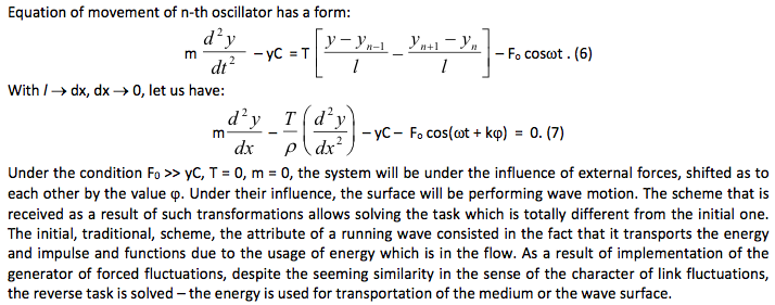
Sergey STREKALOV 1; Igor TYRTYSHNIKOV 2; Lyubov STREKALOVA 3; Sergey PUSHENKO 4
Received: 23/12/2017 • Approved:22/01/2018
ABSTRACT: The article views the state and perspectives of development of wind power and conducts a short analysis of existing constructions of wind energy transformers. A special type of waves is viewed which are a basis of multi-link wave surfaces; terminology used for their description is given. The authors develop mathematical models that connect parameters of these surfaces during interaction with the medium. A capability of multi-link wave surface to create a guided movement of medium flow and a capability of moving the medium are noted. The direction of the usage of attributes of wave surfaces for creation of wind engines is shown. |
RESUMEN: El artículo analiza el estado y las perspectivas del desarrollo de la energía eólica y realiza un breve análisis de las construcciones existentes de transformadores de energía eólica. Se ve un tipo especial de ondas que son la base de las superficies de onda de múltiples enlaces; terminología utilizada para su descripción se da. Los autores desarrollan modelos matemáticos que conectan los parámetros de estas superficies durante la interacción con el medio. Se observa una capacidad de superficie de onda multienlace para crear un movimiento guiado del flujo del medio y una capacidad para mover el medio. Se muestra la dirección del uso de los atributos de las superficies de las olas para la creación de motores eólicos. |

Importance and perspective of the usage of renewable sources of energy are emphasized by the Goals in the sphere of sustainable development, which are in effect starting from January 1, 2016 – in particular, by Goal 7, “Provision of access to cheap, sustainable, and modern sources of energy for everyone” (Goals in the sphere of sustainable development…). Therefore, intensive development of industrial wind power is one of the most important preconditions for sustainable development of each country.
Despite cheaper economic indicators, as compared to traditional sources, realization of the projects for usage of renewable sources of energy has significant perspectives. It is largely determined by the level of development of equipment and technologies for usage of sources of energy and increase of their competitiveness.
Advantages of wind energy are obvious: wind energy is abundant, clean, safe, and reliable as a resource for production of electric energy. The cost of production of electric energy at wind power stations reduces constantly (unlike production of energy with the use of traditional energy sources). Wind power produces electric energy close to a consumer, which reduces its losses and expenses for construction of power lines. The international society notes that renewable energy becomes more profitable and competitive (Sustainable Energy…). The Energy strategy of Russia until 2030 (Energy strategy of Russia…) pays a lot of attention to the necessity for the use of renewable sources of energy and emphasizes the importance of reduction of ecological load from activities of fuel and energy complex. According to the Paris Climate Conference, the most strategic goal is preservation of the growth of the global average temperature by the end of the 21st century within “muck lower” than 2°С over pre-industrial indicators and making efforts for the purpose of limitation of temperature growth at the level of 1.5°С.
One of the main methods of solving this task is wide use of alternative sources of energy. Among the alternative sources of energy, a special role belongs to wind energy. A machine that transforms kinetic energy of wind into mechanic, electric, or heat energy is wing engine. Wind energy turbines occupy only 1% of the territory of the machine, which is very convenient for agriculture: while obtaining the energy, farmers cultivate land and pasture cattle on this territory. Wind engines could be installed on city buildings, where wind speed allows receiving significant capacities from a unit of surface. Recently, the number of sea-based wind engines grew. They are installed on sea shelf and floating platforms (Jonkman, 2007; Tarovik, 2013).
Despite all the diversity of various constructions of wind engines, they could be divided into two large groups: winged with horizontal rotation; rotor, with vertical rotation.
Each of these constructions is peculiar for certain advantages and disadvantages. Rotor wind engines have less complex construction, without the need for wind orientation. One of the main drawbacks of rotor wind engines is low efficiency coefficient, which is in the interval η= 0.2-0.4.
At present, the most popular are winged wind engines with horizontal rotation. An ideal efficient coefficient for such an engine – according to N.E. Zhukovskiy – constitutes 0.593. The most substantial disadvantages of constructions of such type include large expenses for manufacture and installing of the basement for wind engine. These expenses account for 80% of the total cost of construction. Apart from that, there are substantial noise levels, which negatively influences the ecology of the medium.
There are also wind engines that cannot be assigned to any of these two types. One of them is wave wind engines (Strekalov et al., 2004; 2014). A peculiarity of construction of wave wind engines consists in the character of movement of the working body – the wing.
With blade and rotor wind engines, working bodies perform even rotational motion around a motionless axis. A trajectory of each point of a blade is a circumference that lies on the place which is perpendicular to the rotational axis.
Wings of wave wind engines perform rotational motion around moving axes. At that, rotating movement is not even. The wing rotates for a certain angle and then returns to the initial state. Movement of the moving axis is related to the turn of the wing by a certain regularity. This regularity could be performed by means of kinetic connection and by means of resonance of oscillating systems. Combination of movement of moving axes with wing turn leads to constant change of wing attack angle as to the direction of air flow. At each moment of time, wind engine is located along the tangent to the directing wave, performing a wave movement. This was the basis for calling this type of wind engine a wave one. Wave wind engine is a technical system that transforms the energy of wind flow into mechanical energy, with a wing being a working body that performs a movement – under the influence of wind flow – along the tangent of wave surface.
Constructions of this type of wind engines are present in Russia and abroad. In the USA, the W2 Energy Development from Santa Barbara, California (W2 Energy Development…), develops a system consisting of two wings connected by parallel crank mechanism (developer – J. Kelly, patent application dated 2005).
In the Netherlands, a wind engine consisting of parallel worms is being developed. Such system received the name “Ladder mill”. The authors of this construction (Wubbo Ockels) think that they will be able to reduce the cost of energy obtained with such wind engines. An Australian company BioPower designed a BioSTREAM system that has a form of console-fixed blade performed in the form of a shark, tuna, and mackerel fin that converts the flow into the rotation of electric generator shaft (BioSTREAM…). In Russia, A.A. Terentyev and A.G. Terentyev got a patent in 2008 for an engine for utilization of flowing medium energy (Terentyev & Terentyev, 2008). The machine transforms kinetic energy of medium flow into translational and oscillatory movement. Transformation takes place by means of loaded working part with the lateral side across the medium flow. The working part has the form of a wing with hydrodynamic profile. The same constructions are developed in England, Canada, China, and other countries.
We have designed several models of wind engines of wave type, the priority of which related to 1984 (Strekalov, 1986). The construction of wind engine is peculiar for flat wind-sensitive surface that performs wave oscillatory movements under the influence of the wind flow and by means of kinematic connection that transforms efforts to the power-takeoff shaft (Strekalov et al., 2015).
Creation of transforming machines of a wave type is based on the usage of attributes multi-link wave surface (MWS), when one link may be a working part of a wave wind generator.
What is MWS? Let us use one of the simplest means to show wave movement – taking a loose end of a long rope, with other end being fixed tightly, and jerking it up and down. Crests and troughs of waves will appear along the rope; and if the rope were infinitely long, such waves would be called running ones. This way, waves distribute in unlimited medium which has not reflection (Crowford, 1984).
If size of the medium is limited – for example, if a rope is replaced by a guitar string – the running waves will be reflected from both ends. Then, the string oscillations would be a combination of such waves distributing forwards and backwards along the string, creating standing waves.
Waves on strings, ropes, or water surface are cross waves, i.e., oscillations in the medium take place across the direction of wave transmission. If oscillations are parallel to the direction of wave transmission, they are called lateral. Lateral waves include sound waves.
Let us note that certain oscillators that form the medium do not transmit with the waves. They perform oscillations in transverse and lateral directions as to their balance positions. During wave movement, there are several speeds which are totally different values, though related mathematically:
– speed of oscillator fluctuation around its balance position;
– speed of movement of surfaces of the same phase, e.g., crests or troughs.
The simplest theory of waves on the water surface was given by I. Newton in his work “Mathematical Principles of Natural Philosophy” (Newton, 1989), published in 1967; the author notes that “all happens with the supposition that parts of water rise and fall along the vertical lines, but their movement up and down is not direct but circular”.
In the works of J.L. Lagrange (Lagrange, 1950), the wave theory is based on the supposition that parts of wave just oscillate up and down. A Czech scientist, professor of mathematics F. Gerstner created a wave theory, based on the fact that parts of liquid move along circles, and water surface has a form of a cycloid (Miln-Thomson, 1964). Only for very small waves, when wave height is much smaller than their length, a cycloid looks like a sinusoid, and the Gerstner wave turns into a sinusoidal wave.
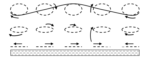
The brothers Weber created their own wave theory (Kudryavtsev, 1948). The results of this theory are given in the book “Study based on experiences”. It was the first experimental study in which waves of various forms, speed of their transmission, and ratio of length and height of the wave were studied systematically. They discovered that the trajectories near the surface are close to circumference, and near the bottom they turn into ellipses, while at the bottom they move horizontally (Figure 1).
Figure 1
Movement of wave parts according to E. Weber
Surface
the d'Alembert wave; it describes all possible movements of the string. Russian scientists also contributed a lot into development of the wave theory. M.V. Ostrogradskiy wrote a work “Theory of waves in a cylindrical vessel” in 1822 (Filippov, 1986).
Ranking supposed that parts move in circles and gave a theory of waves describing it in terms of geometry.
L.D. Landau and E.M. Lifschitz also note in their work “Continuum mechanics” (Landau & Lifschitz, 1953) that liquid particles also move in circles.
The wave equation is one of the main notions. Let us create it on the basis of study of movement of a transverse wave along a string (Crowford, 1984, 58-63).
Let us view vertical shift of У short part of a short string. This part of the string will perform vertical harmonic fluctuations, being a simple harmonic oscillator.
Shift of У changes with time and depends onХ, position of the spot of the string selected for observations over fluctuations. The wave equation connects the shift of У separate oscillator with the distance Х and time t. We will view fluctuation only in the place of the scheme, so our transverse waves on the string will be plainly polarized.
The mass of homogeneous string that accounts for a unit of length, or its linear density, equalsr. Along the string, there is constant tension Т – though it possesses small extensibility.
According to that, we must view a short period and small fluctuations. In this case, equations could be linear. Force of gravity is neglected.
As is seen from Fig. 2, the curved element of the string with the length ds is under the influence of tension Т1, aimed at an angle q to the axis Х from the one end, and of tension Т2, aimed at angle q + dq from the other end.
Figure 2
Shifted element of the string
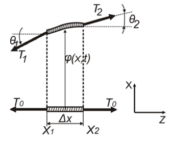
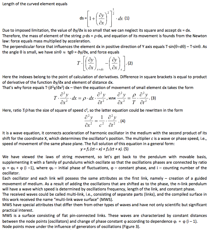
Figure 3
Multi-link wave surface
1 – 13 – multilink nodal points of the wave surface,
“-------” – trajectory node points
Figure 3 shows multi-link wave surface consisting of twelve equal pin-connected links (links: “1-2”, “2-3”, “3-4”, … “12-13”).
The main characteristics of multi-link wave surface are: А – amplitude of oscillations of junctures; l – link length; l – wave length; j – phase constant; n – frequency of fluctuations of oscillators (junctures); u – wave speed; P– pulsation, α – angle of link incline.
Let us view the simplest example when multi-link wave consists of the final number of links pin-connected in junctures. Both ends of a multi-link wave are fixed and there is constant tension T alongside it.
Junctures, or oscillators, of such wave perform harmonic fluctuations in the plane ХОУ.
Let us put a multi-link wave surface in a tense medium. Under the influence of the medium flow, which has energy Е, the system will perform wave movement, as a result of which the junctures (oscillators) will move from the upper to the lower position (Figure 4 shows one half-wave MWS, four links of eight-links of MWS).
Figure 4
MWS under the influence of forced fluctuations
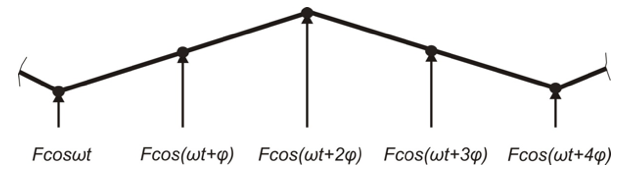
Speed of the wave will be determined by the energy potential that is carried by the flow.
Let us introduce additional condition into the viewed system, namely: let the system experience the influence of forced fluctuations with angle speed w and force F, which influences the juncture (oscillator) perpendicularly to the direction of the wave. Arrows in Figure 4 show directions of efforts F of oscillations generators.
That is, it is possible to say: in the first case, multi-link wave surface allows receiving energy from the moving flow of medium; in the second case, it allows using the energy for moving the medium or the multi-link wave surface. The medium could be viewed as gas, liquid, or solid – depending on the character of its interaction with the link. The possibility for the usage of a feature of multi-link wave surface for the purpose of receipt of mechanical energy from the air flow is realized in the scheme of transformers of the wave type.
An example of interaction of continuous medium with a plate that is parallel to the flow could be the phenomenon that was studied by M.V. Keldysh – it received the name “flatter” (Keldysh, 1985).
Let us try to imagine how sustained vibrations of a wing and ailerons of a flying airplane are preserved. At that, the action of spars that create tense force at wing curve are schematized by springs at which a wing stands.
Let us view the following scheme which models the motion of any wing section: tough wing with aileron is fixed on springs, as is shown in Figure 5.
Wing fixes allows for the free motion up and down (same as the wing section at its curve), but do not allow for changing the attack angle. The aileron can deviate as to the wing. What will be with the wing if it is placed in the air flow?
If the wing with the aileron starts fluctuating in the flow, it will be under the influence of aerodynamic force which depends on the motion parameters. For example, the wing moves downwards. If the aileron deviates upwards as to the wing, additional aerodynamic force appears which goes down and strives to strengthen the wing’s motion. If the aileron deviates downwards as to the wing, the additional aerodynamic force that appears due to the aileron’s deviation will go up and hinder the wing’s motion. Thus, there could be the forms of fluctuations at which additional forced create and sustain vibration and such forms of fluctuations at which aerodynamic forces amortize them.
Figure 5
Wing with aileron
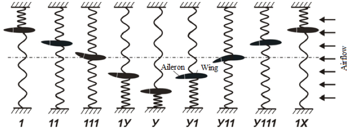
Let us view the system’s fluctuations – such form of motion at which the flatter – sustained fluctuations – is possible.
Let us move the wing from the position of balance (Figure 5) and then we let it be. The wing starts performing fluctuating motion. Successive positions of the wing and the aileron are shown in Figure 5 (1…1Х).
At the initial moment, the wind starts moving under the influence of springs – towards its balance position (11 и 111). The aileron will fall behind the wing, so it will deviate upwards. The wing comes to the medium position (111) after gaining certain speed, so it will pass the balance position and will be moving downwards (1У, У). At this time, the motion slows down. While in the positions 1–111, the springs pull the wing downwards, in the positions 111–У they pull it upwards. The aileron strives to preserve the selected speed and is overcoming the wing.
Let us suppose that by the moment the wing stops (Fig.5.У), the aileron takes a neutral position. After the force of springs stops the wing, the aileron takes the neutral position, and its movement slows down – the aileron will be overcoming the wing (У11–1Х). Then the movement downwards starts, etc.
What influence is done to the fluctuating system from the airflow that meets the wing? These influences are of two forms: firstly, amortizing, which hinder fluctuations and try to quench them, and, secondly, stimulating, which strive to increase fluctuations. Let’s show how they appear.
If the wing moves downwards, it is equal to the air blowing on the wing from below. The attack angle increases and additional uplift appears, which goes upwards, i.e., against the direction of the wing movement. When the wing moves up, it means that the air meets the wing downright. The attack angle decreases (or if it were zero with a motionless wing, there’d be negative angle of attack) and that’s why uplift also decreases. Therefore, during movement of the wing upwards, the force in this direction increases, which equals the appearances of the additional force in the opposite direction. Thus, the uplift produced by fluctuations of the wing is directed against the direction of movement. It strived to quench the fluctuations, i.e., it is amortizing.
Additional uplift appears not so much from oscillating motion of the wing as from deviation of the aileron. As is seen from Figure 5, the aileron deviates upwards during the wing’s downward motion and, on the contrary, it deviates downwards when the wing moves upwards. That’s why the air pressure on the aileron will be directed downwards if the wing moves downwards (the aileron deviates upwards, positions 1–1У), and it will be directed upwards if the wing moves upwards (the aileron deviates downwards, positions У1-1Х).
Therefore, force of air pressure that emerges due to the aileron’s deviation is always directed at the same direction as the wing’s motion. This force tries to increase oscillations – i.e., it is stimulating.
If amortizing forces perform stronger influence than stimulating ones, the oscillations that emerge after the initial deviation will be quenched. If there’s excess of action of stimulating force, oscillations will be happening with growing amplitude – i.e., flatter appears.
Emergence of the flatter under the influence of the air flow could be used for creation of a special class of wind engines, the working body of which, unlike the rotating blade, is an oscillating plate. Such type of wind engines has certain advantages over the traditional ones, as it allows creating constructions with large wind-receiving surface, and, therefore, with larger power. Besides, the form of wind-receiving surface is easier to manufacture.
Let us view the case when MWS performs forced fluctuations, i.e., the link actively influences the environment. It is a reverse task: transformation of mechanism energy directed to the system into the energy of moving flow is conducted by means of direct influence of the link of MWS on air medium.
In a vector form, it is possible to write down that absolute speed could be found as geometric sum of relative wо and transportation и velocity:
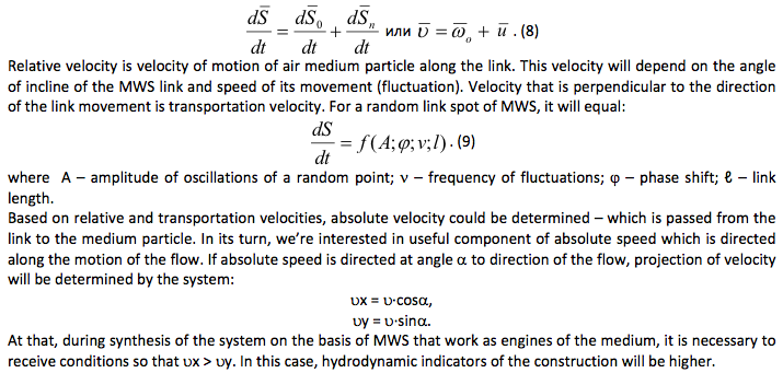
The uplift that influences the MWS link will be changing constantly – and not only by the value but also by the direction. Therefore, the link will be performing fluctuations from the upper position into the lower position under the influence of constant flow. That is, there will be automatic fluctuations, the frequency of which will be determined by speed of movement of the flow and parameters of wave surface.
The basis for the idea for creation of wind power machines of wave type is the usage of the MWS attributes. Theoretical studies show that one link of MWS could be a working body of wind generator. The principle of work of wave wind energy machine, based on functioning of one link of MWS under the influence of air flow could be explained the following way: let us see the wing with the aileron as a link of MWS. Figure 6 shows a possibility for the usage of the phenomenon of flatter for transforming it into rotating motion for the purpose of obtaining mechanical energy from the air flow.
If the tail and nose parts of the aileron are connected to the flywheel so the phase shift will be provided, its fluctuations will leads to the flywheel’s rotation.
Figure 6
Essential scheme of transformation of the aileron’s fluctuations into rotating motion of the flywheel
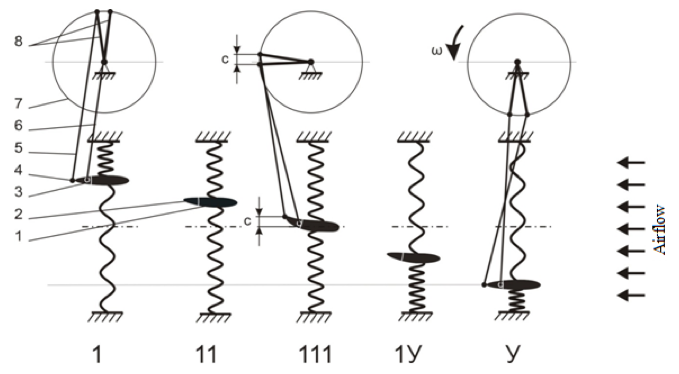
1 – wing, 2 – aileron, 3 – base point of clevis mount, 4 – console point of clevis mount,
5 – console rod, 6 – base rod, 7 – flywheel axis, 8 – cranks, с – shift length.
Let us view the wing with the aileron. Let the wing with the aileron be a link of the MWS. The figure shows five positions of the wing with the aileron: 1, 11, 111, 1У, У. For clarity, let us use three positions of the wing with aileron: 1, 111, and У.
Fixing junction points of crank mechanism rod – basic 3 and console 4 (basic and console oscillators). In their turn, they are related by basic 5 and console 6 rods with flywheel 7 – at that, phase shift is created between points of their fixing to the flywheel. Under the influence of the air flow (direction of the flow is shown in the figure), the wave with the aileron (link of MWS) will perform fluctuations that will lead to the flywheel’s rotation.
The process of transferring the oscillating motion of the MWS link will take place in the following way: influencing the wind receiving surface (in this scheme – the wing with the aileron), the air flow shifts it into the extreme position. Due to the fact that fluctuations of the basic and console oscillators (points of fixation of crank mechanism rods) of wind-receiving surface are shifted as to each other for the value j, with achievement of the extreme position, the angle of incline of wind-receiving surface changes. Due to that, the wind flow will shift it into the opposite extreme position. As a result, there emerges wave motion of wind-receiving surface that is transferred to the wind receiving mechanism. Then, there is transformation into mechanical, electric, and other forms of energy.
We have viewed a mathematical model of functioning of MWS. Such surface possesses unique features. Analysis of general regularities of interaction of the flow with hard surfaces (links of MWS) is performed for the purpose of substantiation of new modifications of transformations of the energy flow.
With the help of corresponding calculation algorithms, the work has built generalized analytical expressions for hydrodynamic loads which influence the surface of solid body in the flow. The MWS capability to create directed movement of the flow and transfer the environment or MWS or to take the flow force with one link and receive the energy from the moving flow of the environment will allow using the energy of the flow and the medium drivers during synthesis of constructive systems that work as transformers.
The principle of work of wave wind engine is based on mutually supplementing interactions of basic and console oscillators of wind receiving surface (wing) with the wind flow. These interactions lead to automatic fluctuating motion of the system, caused by the fact that there is phase difference between the basic and console oscillators caused by kinematic connection. The wave motion is transferred to the receiving mechanism and could be transformed into rotating motion of the rotor which is necessary for functioning of electric energy generator.
The main elements of the wind transformers of the wave type perform alternate (fluctuating) movements. This provides a perspective in synthesis of machines for direct use as drivers of the power machines: linear generators, piston pumps, and various compressors – without intermediary transmission gears.
Analytical research showed expected perspective for reduction of negative influence on the environment (noise and eddy) from the win transformer of the wave type, as all points of wind receiving surface (wing) perform movement with the same speed.
Crowford F. (1984) Waves: study guide. М.: Nauka, Main Publishing House of Physics and Mathematics Literature, 512 p.
D’Alembert J. (1890) Brockhaus and Efron Encyclopedic Dictionary. SPb, 1890 – 1907, vol. I, 350 p.
Energy strategy of Russia until 2030. URL http://minenergo.gov.ru/node/1026
Filippov А.Т. (1986) Many-faced Soliton. Moscow: Ripol Classic, 222 p.
Goals in the sphere of sustainable development. Energy. URL: http://www.un.org/sustainabledevelopment/ru/issues/people/energy/
Jonkman J.M. (2007). Dynamics Modeling and Loads Analysis of an Offshore Floating Wind Turbine. Battelle: Midwest Research Institute, 208 р.
Keldysh M.V. (1985) Mechanics. Moscow: Nauka, 567 p.
Kudryavtsev S. (1948) History of physics. V. 1. From the Antique Physics to Mendeleev / Edited by A.K. Timiryazev. Moscow: State Educational and Pedagogical Publishing House of the Ministry of Education of RSFSR, 536 p.
Lagrange J.L. (1950) Analytical mechanics. Moscow: GITTL. Vol. I. Statics. Dynamics, 594 p. Vol. II. Dynamics (continuation). 440 p.
Landau L.D., Lifschitz E.M. (1953) Continuum mechanics. Moscow: Gostekhizdat, 795 p.
Milne-Thompson L.M. (1964) Theoretical hydrodynamics. Moscow: Mir, 660 p.
Newton I. (1989) Mathematical beginnings of natural philosophy / Ed. by L.S. Polak. Moscow: Nauka, 688 p.
Strekalov S.D. (1986) Certificate of authorship of the USSR No. 1240949, F 03 D 5/00. Wind engine. Application dated May 15, 1984, published June 30, 1986. Bulletin No. 24. Patent database of the USSR. URL: http://patents.su/2-1240949-vetrodvigatel.html
Strekalov S.D. Misharev G.M., Strekalova L.P. (2004) Wave technique. Volgograd: Peremena, 98 p.
Strekalov S.D. Strekalova А.S., Strekalova L.P. (2015) Innovational and demonstrative platforms on the basis of ecological wave wind engines: structure and role in sustainable development of territory. International scientific journal “Alternative energetics and ecology”, no. 13-14, pp. 66-71.
Strekalov S.D., Grishin S.S., Pivchenko А.V., Strekalova А.S. (2014) Regarding the issue of creation of effective ecological wave auto-fluctuating wind engine. Alternative energetics and ecology, no. 4, pp. 26-32.
Sustainable Energy for All. Renewable Energy. URL: http://www.se4all.org/our-vision_our-objectives_renewable-energy
Tarovik V.I., Valdman N.А., Trub M.S., Ozerova L.L. (2013) Development of sea power stations that use renewable sources of energy. Arctic: ecology and economy, no. 2 (10), pp. 34-47.
Terentyev А.А, Terentyev А.G. (2008) Patent of the RF No. 2341679, F 03 B 17/06. Engine for utilization of flowing medium energy. Application dated November 7, 2006, published on May 20, 2008. Register of the patents of the RF. URL: http://bd.patent.su/2341000-2341999/pat/servl/servlet87e5.html
W2 Energy Development Corporation. URL: http://www.yelp.com/biz/w2-energy-development-corporation-santa-barbara
Wubbo Ockels. Happy Energy. URL: http://www.wubbo-ockels.nl/
BioSTREAM. URL: http://www.biopowersystems.com/biostream.html
1. Doctor of Technical Sciences, Professor, Volgograd State University of Architecture and Construction, Volgograd, Russia
2. Doctor of Technical Sciences, Professor, Volgograd State University of Architecture and Construction, Volgograd, Russia
3. PhD, Associate Professor, Volgograd State Agrarian University, Volgograd, Russia
4. Doctor of Technical Sciences, Professor, Don State Technical University, Rostov-on-Don, Russia